Entretoise en aluminium LG – Entretoise à trous, en 2 parties
Propriétés
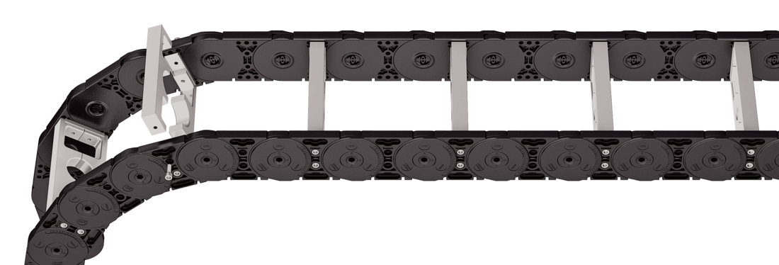
Guidage optimal des câbles dans la ligne de flexion neutre. Version divisée pour guidage de câbles facile. Entretoise disponibles également sans division.
Personnalisation par incrément de 1 mm disponible.
Extérieur / intérieur : vissage facile à desserrer.
Montage des entretoises standard tous les 2 maillons de chaîne (HS : montage partiel)
Montage des entretoises tous les maillons de chaîne (VS : montage intégral)
Bi
75 - 600
mm
de 1 mm largeur par incrément
Dimensions
Dimensions
<p>Le diamètre maximal des câbles dépend fortement du rayon de courbure et du type de câble souhaité. Veuillez nous contacter.</p>
Calcul de la longueur de la chaîne
Longueur de la chaîne Lk: Lk ≈ LS/2 + LB
Longueur de la chaîne Lk arrondie au pas de la chaîne t
Calcul de la largeur d’entretoise
Largeur d’entretoise BSt: BSt = Σ D + Σ c + 2 a0
<table class="table">
<thead>
<tr>
<!-- Reihenfolge gemäß Kundenwunsch -->
<th class="t"><strong>t</strong><br>[mm]</th>
<th class="dmax red"><strong>D<sub>max</sub></strong><br>[mm]</th>
<th class="dmin"><strong>D<sub>min</sub></strong><br>[mm]</th>
<th class="hg"><strong>h<sub>G</sub></strong><br>[mm]</th>
<!-- Bi Spalte nur anzeigen wenn einzelner Wert oder Range -->
<th class="bi"><strong>B<sub>i</sub></strong><br>[mm]<sup>*</sup></th>
<th class="bst red"><strong>B<sub>St</sub></strong><br>[mm]</th>
<!-- Bk und BEF für alle Ketten -->
<th class="bk"><strong>B<sub>k</sub></strong><br>[mm]</th>
<th class="bef"><strong>B<sub>EF</sub></strong><br>[mm]</th>
<th class="cmin"><strong>c<sub>min</sub></strong><br>[mm]</th>
<th class="a0min"><strong>a<sub>0</sub> min</strong><br>[mm]</th>
<!-- KR Spalte nur anzeigen wenn einzelner Wert oder Range -->
<th class="qk50"><strong>q<sub>k</sub> 50%</strong><br>[kg/m]<sup>**</sup></th>
</tr>
</thead>
<tbody>
<tr>
<!-- Reihenfolge gemäß Kundenwunsch -->
<td class="t">95</td>
<td class="dmax red">50</td>
<td class="dmin">12</td>
<td class="hg">80</td>
<!-- Bi Spalte nur anzeigen wenn einzelner Wert oder Range -->
<td class="bi">
75 - 600
</td>
<td class="bst red">
78 - 603
</td>
<!-- Bk und BEF für alle Ketten -->
<td class="bk">BSt + 39</td>
<td class="bef">BSt + 39</td>
<td class="cmin">4</td>
<td class="a0min">11</td>
<!-- KR Spalte nur anzeigen wenn einzelner Wert oder Range -->
<td class="qk50">3.89 - 8.25</td>
</tr>
</tbody>
</table>
* de1 mm largeur par incrément** Hole ratio of the hole stay approx. 50 %
KR [mm]
140
170
200
260
290
320
380
qk 50%:
3.89 - 8.25 mm
Hole ratio of the hole stay approx. 50 %
Exemple de commande
MC0950
Série
•
400
Bi [mm]
•
LG
Type d’entretoise
•
200
KR [mm]
-
2850
Lk [mm]
HS
Pos. entretoises
Éléments de raccord
Éléments de raccord
Couple de serrage recommandé : 27 Nm pour vis cylindriques ISO 4762 - M8 - 8.8
Point de raccord F – Point fixe M –Point mobile
Type de raccord U – Raccord universel
Exemple de commande
UMB
UMB
Pièce de raccord
•
F
•
M
Point de raccord
U
U
Type de raccord
Nous recommandons d’utiliser des décharges de traction au niveau de point mobile et du point fixe.
Point de raccord F– Point fixe M– Point mobile
Type de raccord A – Fixation vers l’extérieur (standard) I – Fixation vers l’intérieur F – Raccord à bride
Surface de raccord I– Surface de raccord interieure A– Surface de raccord exterieure
Exemple de commande
Plastique / acier
Plastique / acier
Pièce de raccord
•
F
•
M
Point de raccord
A
A
Type de raccord
A
I
Surface de raccord
Nous recommandons d’utiliser des décharges de traction au niveau de point mobile et du point fixe.