Guide channels
Reliable unrolling and optimum gliding for long travel lengths
Guide channels are important elements for the reliable functioning with long travel lengths. The upper run of the cable carrier slides on the lower run and on the sliding area of the guide channel behind the fixed point. Guide channels prevent the upper run from slipping off the lower run, ensuring quiet running with low wear. For vertical applications such as elevators or storage and retrieval systems, a vertical channel provides optimum guiding.
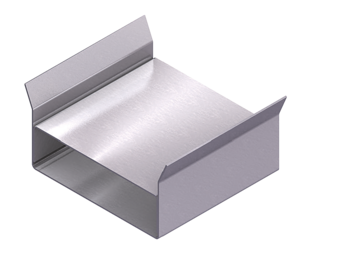
Standard channel
- Simple version with customized fixing options.
- Zinc plated sheet steel or stainless steel.
- Standard lengths.
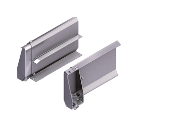
Steel Guide System (TKSG)
- Modular system with optimized design for long travel lengths.
- Zinc plated sheet steel or stainless steel.
- Easy installation.
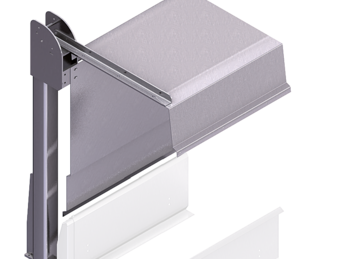
Channel Enclosure
- Optimum protection against external influences.
- Easy access for inspection.
- Modular design.
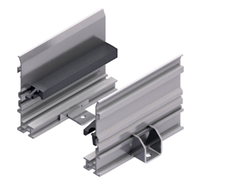
Alu Guide System (TKAL)
- Modular system with many mounting options.
- Standard lengths and sets.
- Lightweight design for high speeds.
Easy Guide System (TKEG)
- Flexible use in many areas of application.
- Made of zinc plated sheet steel or stainless steel.
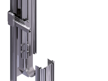
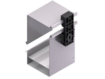
Vertical Guide System (TKVG)
- Ready-to-install channel system made of aluminum.
- Standardized module.
- Easy installation.
- For elevators, storage and retrieval systems and many other applications.
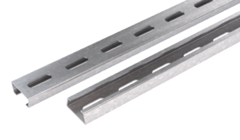
Assembly profiles
- Assembly profiles with sloping sides can be used for all guide channels for fastening
- Lengths in 50 mm grid possible
Installation Dimensions
One-sided arrangement – with lower driver connection and reverse bending radius (standard)

Calculating the channel length
Channel length LKA: LKA = LS + UB + L1
Calculating the connection height
Connection height H: H = 3 hG
Calculating the slide support length
Slide support length LKA': LKA' = LS / 2
One-sided arrangement – high connection

Calculating the channel length
Channel length LKA: LKA = LS + UB + L1
Connection height high connection
Connection height H: H = 2 x KR + hG
Calculating the slide support length
Slide support length LKA': LKA' = LS / 2
Opposite arrangement – with lower driver connection and reverse bending radius (standard)

Calculating the channel length
Channel length LKA: LKA = LS + 2 UB + X
Calculating the connection height
Connection height H: H = 3 hG
Calculating the slide support length
Slide support length LKA': LKA' = X – 2 L1
Opposite arrangement – high connection

Calculating the channel length
Channel length LKA: LKA = LS + 2 UB + X
Connection height high connection
Connection height H: H = 2 x KR + hG
Calculating the slide support length
Slide support length LKA': LKA' = X – 2 L1