Guide channels
Reliable unrolling and optimum gliding for long travel lengths
Guide channels are important elements for the reliable functioning with long travel lengths. The upper run of the cable carrier slides on the lower run and on the sliding area of the guide channel behind the fixed point. Guide channels prevent the upper run from slipping off the lower run, ensuring quiet running with low wear. For vertical applications such as elevators or storage and retrieval systems, a vertical channel provides optimum guiding.
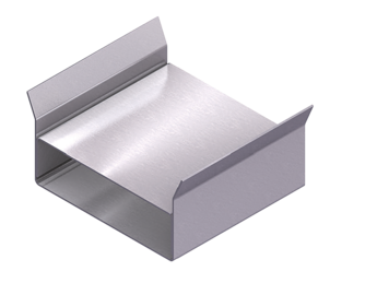
Kanał standardowy
- Prosta wersja z dostosowanymi opcjami mocowania.
- Blacha stalowa ocynkowana lub stal nierdzewna.
- Standardowe długości.
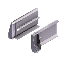
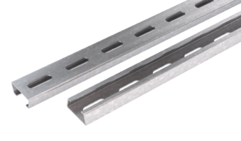
System prowadnic stalowych (TKSG)
- System modułowy o zoptymalizowanej konstrukcji do długich odległości przesuwu.
- Ocynkowana blacha stalowa lub stal nierdzewna.
- Łatwa instalacja.
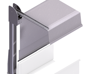
Obudowa kanału
- Optymalna ochrona przed czynnikami zewnętrznymi.
- Łatwy dostęp do kontroli.
- Modułowa konstrukcja.
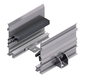
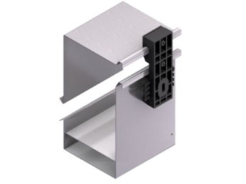
System prowadnic aluminiowych (TKAL)
- System modułowy z wieloma opcjami montażu.
- Standardowe długości i zestawy.
- Lekka konstrukcja zapewniająca duże prędkości.
System Easy Guide (TKEG)
- Elastyczne zastosowanie w wielu obszarach.
- Wykonane z blachy stalowej ocynkowanej lub stali nierdzewnej.
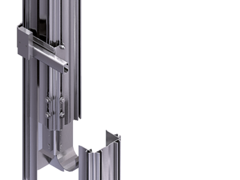
System prowadnic pionowych (TKVG)
- Gotowy do montażu system kanałów wykonany z aluminium.
- Standaryzowany moduł.
- Łatwa instalacja.
- Do wind, systemów magazynowania i pobierania oraz wielu innych zastosowań.
Profile montażowe
- Profile montażowe o pochyłych bokach mogą być stosowane do wszystkich kanałów prowadzących w celu mocowania
- Dostępne długości w odstępach co 50 mm
Installation Dimensions
One-sided arrangement – with lower driver connection and reverse bending radius (standard)

Calculating the channel length
Channel length LKA: LKA = LS + UB + L1
Calculating the connection height
Connection height H: H = 3 hG
Calculating the slide support length
Slide support length LKA': LKA' = LS / 2
One-sided arrangement – high connection

Calculating the channel length
Channel length LKA: LKA = LS + UB + L1
Connection height high connection
Connection height H: H = 2 x KR + hG
Calculating the slide support length
Slide support length LKA': LKA' = LS / 2
Opposite arrangement – with lower driver connection and reverse bending radius (standard)

Calculating the channel length
Channel length LKA: LKA = LS + 2 UB + X
Calculating the connection height
Connection height H: H = 3 hG
Calculating the slide support length
Slide support length LKA': LKA' = X – 2 L1
Opposite arrangement – high connection

Calculating the channel length
Channel length LKA: LKA = LS + 2 UB + X
Connection height high connection
Connection height H: H = 2 x KR + hG
Calculating the slide support length
Slide support length LKA': LKA' = X – 2 L1