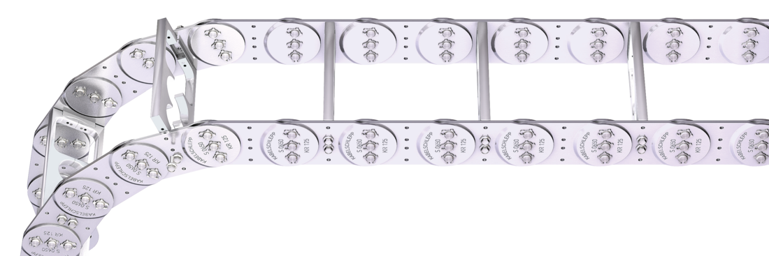
Optimum cable routing in the neutral bending line. Split version for easy cable routing. Stays also available unsplit.
Available customized in 1 mm grid.
Inside/outside: Threaded joint easy to release.
Stays on every 2nd section, standard (HS: half-stayed)
Stay arrangement on each chain link (VS: fully-stayed)
Bk
70 - 500 mm
w 1 sekcje szerokości mm
Wymiary
Wymiary
The maximum cable diameter strongly depends on the bending radius and the desired cable type. Please contact us.
Obliczanie długości prowadnika kablowego
Cable carrier length Lk: Lk ≈ LS/2 + LB
Cable carrier length Lk rounded to pitch t
Obliczanie szerokości poprzeczki
Stay width BSt: BSt = Σ D + Σ c + 2 a0
<table class="table">
<thead>
<tr>
<!-- Reihenfolge gemäß Kundenwunsch -->
<th class="t"><strong>t</strong><br>[mm]</th>
<th class="dmax red"><strong>D<sub>max</sub></strong><br>[mm]</th>
<th class="dmin"><strong>D<sub>min</sub></strong><br>[mm]</th>
<th class="hg"><strong>h<sub>G</sub></strong><br>[mm]</th>
<th class="hgdash"><strong>h<sub>G'</sub></strong><br>[mm]</th>
<!-- Bi Spalte nur anzeigen wenn einzelner Wert oder Range -->
<th class="bi"><strong>B<sub>i</sub></strong><br>[mm]</th>
<th class="bst red"><strong>B<sub>St</sub></strong><br>[mm]<sup>*</sup></th>
<!-- Bk und BEF für alle Ketten -->
<th class="bk"><strong>B<sub>k</sub></strong><br>[mm]</th>
<th class="bef"><strong>B<sub>EF</sub></strong><br>[mm]</th>
<th class="cmin"><strong>c<sub>min</sub></strong><br>[mm]</th>
<th class="a0min"><strong>a<sub>0</sub> min</strong><br>[mm]</th>
<!-- KR Spalte nur anzeigen wenn einzelner Wert oder Range -->
<th class="qk50"><strong>q<sub>k</sub> 50%</strong><br>[kg/m]<sup>**</sup></th>
</tr>
</thead>
<tbody>
<tr>
<!-- Reihenfolge gemäß Kundenwunsch -->
<td class="t">65</td>
<td class="dmax red">34</td>
<td class="dmin">10</td>
<td class="hg">50</td>
<td class="hgdash">56</td>
<!-- Bi Spalte nur anzeigen wenn einzelner Wert oder Range -->
<td class="bi">
35 - 465
</td>
<td class="bst red">
53 - 483
</td>
<!-- Bk und BEF für alle Ketten -->
<td class="bk">BSt + 17</td>
<td class="bef">BSt + 22</td>
<td class="cmin">4</td>
<td class="a0min">9</td>
<!-- KR Spalte nur anzeigen wenn einzelner Wert oder Range -->
<td class="qk50">3.96 - 6.46</td>
</tr>
</tbody>
</table>
* w1 sekcje szerokości mm** Hole ratio of the hole stay approx. 50 %
KR [mm]
75
95
115
125
135
145
155
175
200
250
300
400
qk 50%:
3.96 - 6.46 mm
Hole ratio of the hole stay approx. 50 %
Przykład zamówienia
S0650
Typ
•
180
BSt [mm]
•
LG
Wariant poprzeczki
•
135
KR [mm]
•
St
Materiał
-
1430
Lk [mm]
HS
Układ poprzeczek
Złączki końcowe
Złączki końcowe
Connection point F – fixed point M – driver
Connection type A – threaded joint outside (standard) I – threaded joint inside H – threaded joint, rotated 90° to the outside K – threaded joint, rotated 90° to the inside
Connection surface I – connection surface inside (standard) A – connecting surface outside
Caution: The standard connection variant FAI/MAI is only possible from Bk of 70 mm.
Przykład zamówienia
Steel
Steel
Złączka końcowa
•
F
•
M
Punkt połączenia
A
A
Typ połączenia
I
I
Powierzchnia połączenia
We recommend the use of strain reliefs at the driver and fixed point.