Hinged belt conveyors
Proven for a wide range of disposal tasks
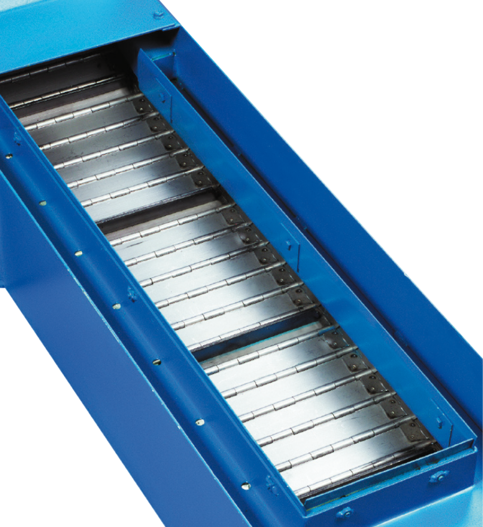
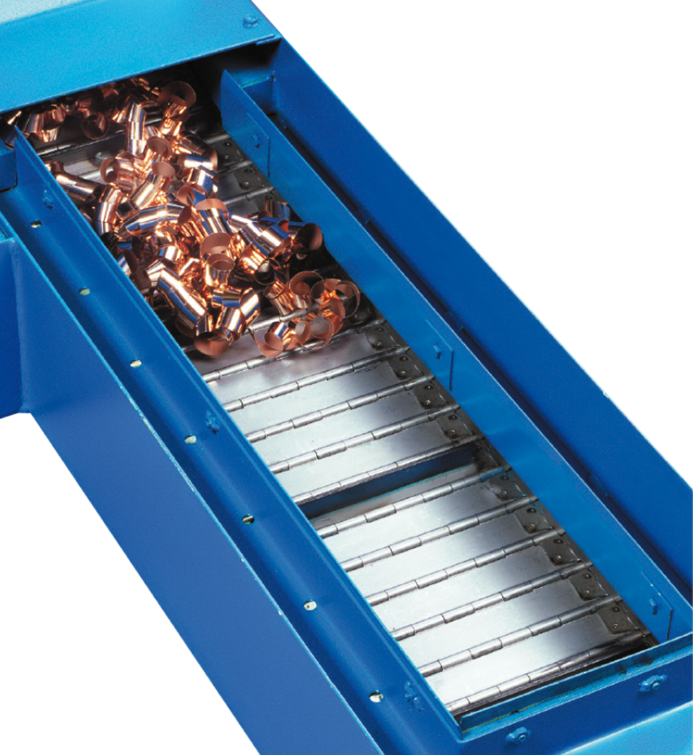
Transportation of the material takes place on the upper trough of a revolving hinged belt. Carriers ensure transport of the material in the inclined section. For wet processing the cooling lubrications are collected in the conveyor housing and can be fed back into the machine circuit via an optionally available coolant tank or a pump station. Our hinged belt conveyors can be used either as stand-alone conveyors at machine tools, or as linked conveyor systems. Depending on the design, the material to be conveyed is brought to the required height at a defined incline and then discharged.
Structure
- Stable sheet metal construction
- Standardized housing cross-section with variable width
- Robust worm gear motor with torque arm
- Customized discharge height
- Customized incline standards – 30°, 45° and 60°
- Floor mounting or as a push-in version into the machine base
Dimensions of conveyor housing


Standard version

* The box height can be retracted on request.
Variable dimensions:
BSch = Hinged belt width
BK = Box width
BAG = Feed width
HB = Panel height
AAV = Distance between axles, vertical
LAG = Feed length
LAW = Discharge length
LG = Total length of the conveyor
α = Incline angle
Design-dependent dimensions:
HK = Box height
HKE = Retracted box height
LA = Length of the tail (discharge, incl. tensioning distance)
LU = Length of the tail (feed)
The tensioning station is located at the discharge.
| Type | HB [mm] | HK [mm] | HKE* [mm] | LAW min [mm] | LA [mm] | LU [mm] | ||
|---|---|---|---|---|---|---|---|---|
| SRF 040 | 40 | 60 | – | 140 | 110 | 350 | 180 | 73 |
| SRF 063 | 40 | 80 | 120 | 216 | 153 | 500 | 240 | 111 |
| SRF 100 | 150 | 250 | – | 360 | 260 | 850 | 600 | 185 |
| SRF 150 | 150 | 250 | 350 | 540 | 390 | 1000 | 600 | 275 |
All electrical components in CE design.
Additional local specifications on request. Please contact our support-team.
Dimensions of the hinged belt
Manufactured of strip steel, the hinged belt plates have roller-formed hinge eyes, and are connected by means of axles to the side chains (which are designed as hollow pin chains), thus forming a hinged belt assembly.


| Type | t [mm] | SSCH [mm] | HS [mm] |
|---|---|---|---|
| SRF 040 | 40 | 1.5 | 20 |
| SRF 063 | 63 | 3 | 35 |
| SRF 100 | 100 | 3.5 | 60 |
| SRF 150 | 150 | 5 | 100 |
Definitions:
t = Pitch
BSch = Hinged belt width
SSCH = Plate thickness of the belt
HS = Height of the side board
BK = Box width
BAG = Feed width
Dimensions as a function of the hinged belt width
| Type | BSCH [mm] | BK [mm] | BAG [mm] |
|---|---|---|---|
| SRF 040 | 100 | 175 | 80 |
| 150 | 225 | 130 | |
| 200 | 275 | 180 | |
| 250 | 325 | 230 | |
| 300 | 375 | 280 | |
| 400 | 475 | 380 | |
| 500 | 575 | 480 | |
| 600 | 675 | 580 | |
| SRF 063 | 150 | 270 | 130 |
| 300 | 420 | 280 | |
| 400 | 520 | 380 | |
| 500 | 620 | 480 | |
| 600 | 720 | 580 | |
| 1050 | 1170 | 1030 | |
| 1650 | 1770 | 1630 | |
| 2100 | 2220 | 2080 |
| Type | BSCH [mm] | BK [mm] | BAG [mm] |
|---|---|---|---|
| SRF 100 | 150 | 300 | 120 |
| 300 | 450 | 270 | |
| 400 | 550 | 370 | |
| 500 | 650 | 470 | |
| 600 | 750 | 570 | |
| 1050 | 1200 | 1020 | |
| 1650 | 1800 | 1620 | |
| 2100 | 2250 | 2070 | |
| SRF 150 | 300 | 490 | 250 |
| 400 | 590 | 350 | |
| 500 | 690 | 450 | |
| 600 | 795 | 550 | |
| 700 | 890 | 650 | |
| 1050 | 1240 | 1000 | |
| 1650 | 1840 | 1600 | |
| 2100 | 2290 | 2050 |
Hinged belt designs
Various hinged belt designs are available for different operating conditions:
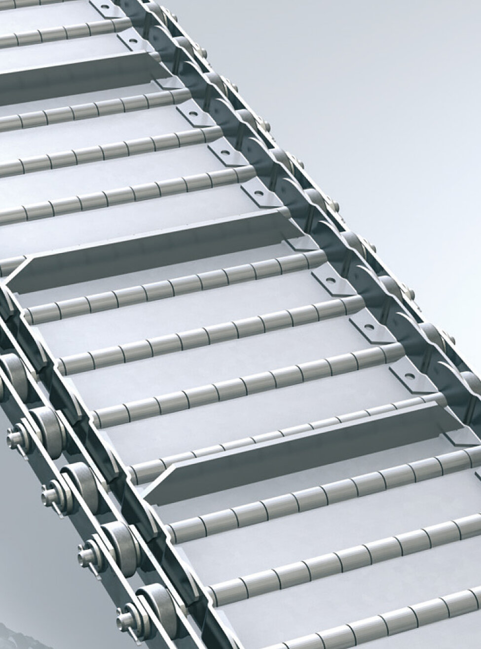
Hinged belt (standard)
for dry materials and chips with a low proportion of coolan
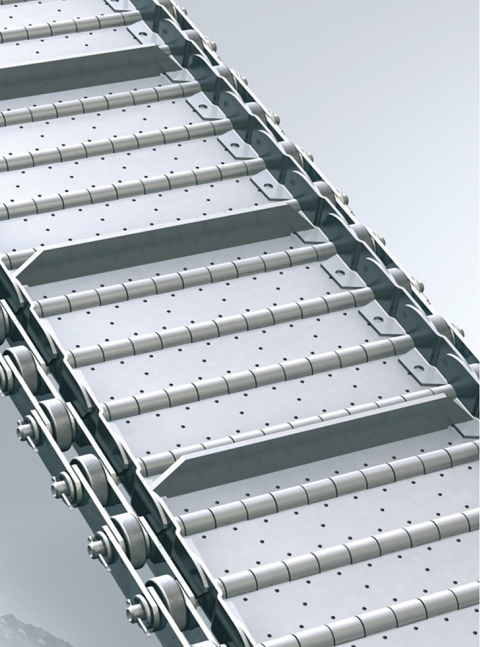
Hinged belt with perforations
for preseparation of coolant for materials with a high proportion of coolant
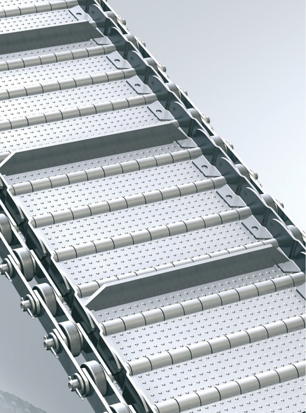
Hinged belt conveyor with corrugations
for transporting “sticky” parts
- Optimum chip leak tightness
- No attack surfaces for chips and stamped parts
- Robust design
- Prevents jamming of the conveyed material
